In engineering, fit means clearance between two connection components or mating materials. The use of engineering fit defines either two parts moving relatively due to clearance fit and working completely for tight interference fitting.
Limits and fits are used for different joining connections and are mainly used for size regulation of mating shafts and holes for proper working. There are three main types of fits used: clearance, transition, and interference. Here we will cover details, features, and related factors.
What’s an engineering fit?
- Engineering fits are employed as a component of geometric dimensioning and tolerancing as an assembly part after designing. For engineering, fit is the clearance between two mating parts, and the size of the clearance defines whether the parts can, at one end of the spectrum, move away from each other or are temporarily or permanently connected.
- Engineering fits are defined as shaft and hole pairings that are not only used for round-shaped parts. ISO standards define engineering fits, and in North America ANSI is also used.
- Engineering fits are commonly used in manufacturing to make parts that are configured with each other to operate one or more functions and operations.
- Their interaction affects their function in assembly. The relation between mating parts is called a fit, and it defines how they are connected.
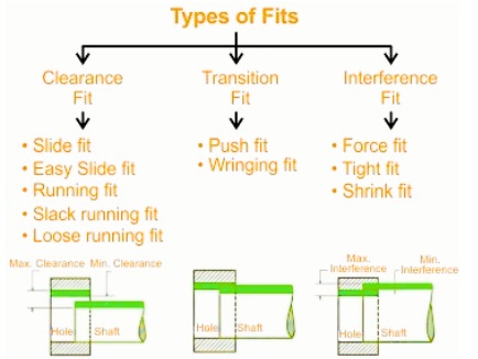
Difference between maximum and minimum clearance
- The maximum clearance of fits is the difference between the upper bound of the orifice diameter and the lower shaft diameter.
maximum clearance = maximum orifice diameter – minimum shaft diameter
- Minimum clearance is the difference between the lower bound of the orifice diameter and the upper bound of the shaft diameter.
minimum clearance = minimum orifice diameter – maximum shaft diameter
- The maximum clearance for loose fit is higher than 0, and the tight fit is a negative value for maximum and minimum clearance.
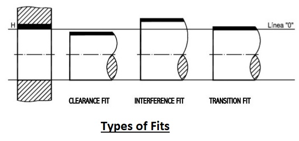
Types of Fit
- Clearance fit
- Interference fit
- Transition fit
Interference Fit
- Interference fit is an engineering fit where high frictional force strongly controls hole mating parts. It is also called a friction fit.
- Interference fits tightness come from negative clearance. So mating parts press against each other. Basically, mating parts or surfaces are deshaped inwards due to contact pressure.
- Such as in a hole and shaft system, the hole is small compared to the shaft in an interference fit.
- The shaft is press-fit into the hole through the application of a hammer.
- Shrink fitting is also used for making interference fits. In this method, one part is cooled or heated so it contracts or expands for negative clearance to change to positive clearance.
- After finding parts, each of their temperatures normalizes. As a result, the thermal shrinkage or expansion makes a tight interference fit.
- Clearance in interference is -0.001mm to -0.042mm.
Types of Interference Fit
Force fit:
- In a force fit, one component is pressed into another to make one unit, and a high value of force is used for fitting parts.
Tight fit:
- It has low interference as compared to force fit; tight fitting needed certain force but less than force fit. Fitting of gears on shaft is also called a tight fit.
Shrink fit:
- In this type, heat is applied to one mating component and then assembled over another part to make one unit. Permanent mounting of gears on a shaft and mounting of a train wheel on a shaft are types of shrink fit.
Transition Fit
Types of Clearance Fit
Slide fit:
- It is employed for high accuracy and low clearance, providing a mating component for free movement, such as a tailstock of a lathe machine.
Easy slide fit:
- It provides higher clearance than other types and is used where accuracy is not important.
Loose running fit:
- It is used for low-accuracy applications and makes higher clearance than other clearance fits.
Free running fit:
- It is used for moderate-level accuracy, helping parts movement.
Basis of Fits
- There are 2 basic systems for tolerance value to the shaft and hole that are called the hole basis system and the shaft-basis system.
Hole-basis system
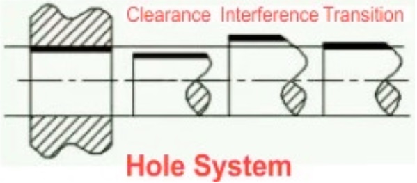
- In a hole basis system, different clearance and interference values are obtained through different shafts in a single hole with a low deviation of zero. Hole size is base size, and clearance is applied on the shaft dimension.
- • The H symbol denoted this system and features, as holes can be drilled with standard drills. Shafts are turned to the required dimensions and commonly used. a
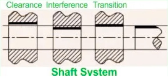
Shaft-basis system
- In this style, different clearances are obtained with different holes in a single shaft and have an upper deviation of zero. The shaft size is base, and the clearance is applied on hole dimensions. It is denoted with H and is part of industries with the use of semi-finished raw materials.
How to Choose Fit for Projects
Application
- The applications define the use of fit,, like if you needed free rotation, a fixed connection, and a tight, accurate points having low motion. Certain functions define the use of certain fi,ts, like clearance, interference, or transition.
Load and Stress Demand
- Interference is good for high-load transmission, and torque and clearance fits are good to use when there is low-load demand. Transition fits provide a good location having load-carrying features.
Material
- Material of connection components is important for the use of fit. Thermal expansion is different for different materials; which can change the fitting. Considered strength and ductility for high interference to damaging components.
Manufacturing Processes
- The production process tolerance affects the use of fitting options, like CNC machines used for tight tolerances as compared to casting, so follow the manufacturing features before using any certain fit. Tighter tolerances increase the manufacturing cost