Fluid dynamics principles are seen in different latest devices and inventions. It is commonly seen in modern toilets to rocket propulsion. Fluid dynamics is an important factor for products used in engineering. The fluid coupling is an important factor, like other engineering concepts. In this post, we will cover details for fluid coupling and related factors.
What Is Fluid Coupling?
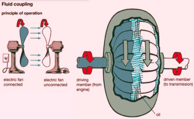
- A fluid coupling, also called a hydraulic coupling, is a hydrodynamic device used for the transmission of rotational mechanical power.
- It is used for automobile transmission systems for the replacement of mechanical clutches.
- It is used in marine and industrial machine drives and for variable speed applications, and controlled start-up without shock loading of the power transmission system.
- Hydrokinetic drives are different from hydrostatic drives, like hydraulic pump and motor mixtures.
- Fluid coupling is a torque-transmitting couplings that employ hydraulic oil. They are different from torque converters, where input torque equals output torque.
- Fluid coupling is more effective than torque converters and comes with 2 to 4 percent losses.
- Fluid coupling is used for providing acceleration control, torque limiting control, load sharing control, and speed control.
- Constant power was also applied, and the power in load decreased with speed. The difference between input power and output power is power dissipated as losses in coupling.
Fluid coupling components
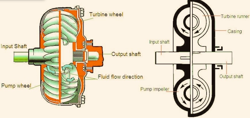
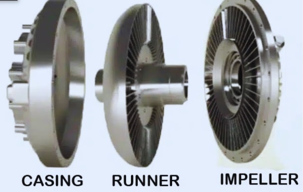
Fluid coupling comes with three main components and hydraulic fluid.
- Housing, also called a shell, comes with fluid and turbines.
- It has two turbines, one configured with an input shaft that is called a pump or primary wheel input turbine.
- second connected with the output shaft, that is, the turbine, the output turbine, and the secondary wheel
- driving turbine It, also called a pump, is rotated with a prime mover that is an internal combustion engine.
- Impeller motion affects both outward linear and rotational motion for fluid.
- Hydraulic fluid is directed with a pump that is designed to apply forces low in the direction of the output turbine.
- The difference in angular velocity of the input phase and output phase causes a net force on the output turbine, resulting in torque. As a result, rotate the direction of the pump.
- Fluid motion is toroidal; it moves in one direction along the paths that can be seen on the surface of the torus.
- If a difference exists between input and output angular velocity, motion comes with a poloidal component.
- If input and output stages come with identical angular velocity and do not have net centripetal forces, the motion of fluid is in a circular direction and the same axis as the axis of rotation. There is no flow of fluid from one turbine to the other.
Fluid Coupling Specifications
- It comes with two bladed wheels that are connected in a hydraulic way.
- power transmits without wear and has high input speed, providing mechanical transmission
- Its fluid in the working state is a connection component.
- Fluid quantity can change during machine starting time for controlling startup features and power transmission.
- hydrodynamic devices provide longer working life through dampening torsional vibration and driveline shock.
- fill level variations control-driven machine speed. Provide protection for the drive and machine from being affected by torque spikes.
- Slip value is about 100 percent, providing motor stability.
Fluid Couplings Working
- Before the use of fluid coupling, the vehicle comes with a manual gearbox. The clutch, which makes a connection with the engine and transmission, is operated by the driver for manual transmission.
- A vehicle having a manual gearbox can stall if stopped without a clutch.
- For accurate working of fluid coupling, fluid dynamics and hydrokinetics are used as the base for fluid coupling features.
- It is different from hydrostatic systems like hydraulic pumps. fluid coupling made with two wheels having blades that face one another but do not have a connection.
- The impeller that is one wheel connected with the power supply. The impeller provides power to the turbine. That is then delivered to transmission.
- The turbine that is output rotates slowly as compared to the impeller, also called input. Energy is transferred through the system with the output spinning as a result of the fluid flowing in.
- The oil-filled assembly comes with wheels that hold it in position.
Fluid Coupling Working Principle
- The impeller starts the centrifugal pump oil static runner when the motor moves to running speed.
- conical impeller baffle diffused oil transmission, generating slow torque increment, providing motor to move fast with running speed
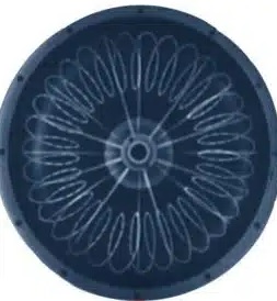
- When oil is pumped into the working location, the oil continuously circulates between the impeller and the runner, making a flow area as the helical spring makes a ring.
- When the transmitted torque is at the resisting torque value, the runner rotates and accelerates the operating load.
- Time needed for getting full speed is based on load inertia, resisting torque, and torque transmitted to the fluid coupling.